Electrical Engineering Comes to KDE with KTechLab

The first version of KTechLab was released a couple of weeks before the new year. While only at version 0.1 it already contains a lot of functionality for developing and simulating electronic circuits. Currently KTechLab can create circuit diagrams for electronics and flow diagrams for PIC chips (a family of programmable chips). It can even compile and run your flow diagrams in a circuit.
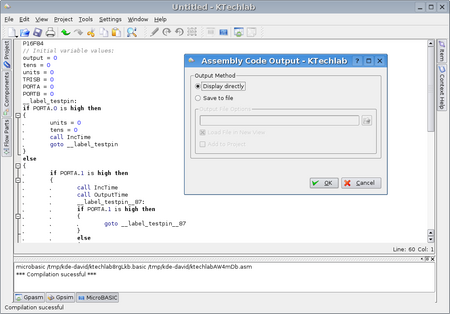
KTechLab includes a whole programming language called MicroBASIC and associated compiler for programming PICs. It can compile the flow diagrams into MicroBASIC and from there into an assembly language compatible with MPASM as used by the manufacturer of PICs. The assembly language can be compiled into a machine code suitable and compiler for feeding into PICs.
You can find KTechLab at http://ktechlab.org/
Screenshots in this article are taken from http://ktechlab.org/screenshots/
Installing KTechLab
As a new program there are no packages for KTechLab yet but you can download it from http://ktechlab.org/download/ktechlab-0.1.2.tar.bz2 and compile as described at http://ktechlab.org/download.php
KTechLab needs two libraries which you may not have, gpsim 0.21
http://www.dattalo.com/gnupic/gpsim.html (required for building) and gputils
http://gputils.sourceforge.net/. gpsim 0.21 is quite new and may not be included with your distribution. Unfortunately compiling gpsim requires that you install gtk-config which will be in a package called libgtk1.2-dev or similar and gtkextra-config which I found in a package called libgtkextra-dev using Debian.
A First Look at KTechLab
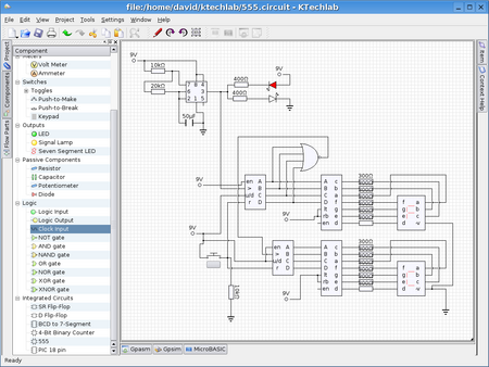
KTechLab uses the KMDI interface familiar to users of Kate or KDevelop. (You can change this layout but this seems to cause problems and KMDI is the most usable.) Diagrams and code are displayed as tabs and each diagram is saved as an XML file using a custom language and a file extention of .flowcode or .circuit. You can group together diagrams and code files into projects which makes a file with a .ktechlab extention that points to the other files but I wonder if it would be more intuitive to just have one file for all your diagrams and code.
Around the edge of the canvas you'll find electrical components which can be dragged onto circuit diagrams and flow parts for flow chart diagrams. I usually find it best to keep this left hand sidebar open all the time when working, you can do this by clicking on the "Overlap" button (square icon) at the top of the sidebar. On the right hand side is an Item sidebar which gives information and lets you set properties of the currently selected item in the diagram. There is also a context help sidebar giving a helpful description of the currently selected item in the diagram. Many Free Software applications are criticised for their lack of documentation so it is refreshing to find one which goes out of its way to provide extra documentation.
Having worked on Umbrello which also draws diagrams I find myself jealous at the intelligent way the connections joining diagram items route themselves. You can also do manual connection routing if you are not happy with the automatic routing. Diagrams can not currently be resized or zoomed, maybe this will be added in future versions (although it is actually quite difficult to get QCanvas drawings to be resizable on the top and left hand sides).
Using KTechLab
A flowchart is probably the best place to start. In the top left or the diagram is a picture of the PIC chip, this show its initial settings, it is not part of the flowchart itself. You can change these initial settings by clicking on each connects of the PIC to turn it on or off, clicking and dragging left or right will set it to be an input or an output. Flowcharts need a start and end which you can drag in from the flow part sidebar. You can then drag in any of the other flowchar actions and connect them together. Dragging in a subroutine adds a large diagram item into which you can put other items.
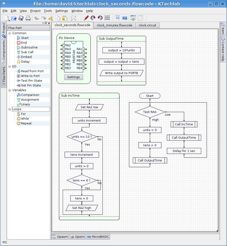
Once you have your flowchart you can convert it into microbasic, assembly code or directly into machine (hex) code by using the buttons on the right hand side of the toolbar (or from the Tools menu).
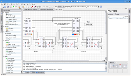
Now we can make a new circuit diagram. The Components sidebar contains assorted electrical items that can be dragged onto the diagram. At the very bottom is a PIC 18 Pin item. If you add this to a diagram it can be associated with the flowchart you just made (or one of its code representations). Click on the PIC and point it towards the file with your flowchart by editing the filename box in the toolbar. If you now run the PIC by clicking the play button below it the circuit should run according to your flow diagram, you can see the output in the gpsim box at the bottom of the diagram.
Conclusion
KTechLab is already a very advanced program, there are a few small beasties in it for example I was unable to delete or reroute a connections between two diagram items, but these will likely be fixed soon. I look forward to this program being available in KDE 4.
What can be expected in the future?
Aside from polishing and massive optimisations, more components and flowparts, wider PIC language support, and better in-circuit simulation of PICs, there will also be the ability to create subcircuits, a waveform viewer, and circuit interfacing with computer peripherals such as the serial port.
But perhaps the most interesting feature scheduled for development, though, will be the Mechanics simulator. This will provide a mechanism to simulate real-life mechanical devices, which are controlled by circuits. Each mechanical entity in the 2D view will consist of one or more "frameworks" attached together, along with periphereals attached to a framework that act as an interface between the simulation and a circuit. Such a periphereal could be a collision detector, for example, or a set of wheels. By building up a mechanical environment, and connecting it with circuits constructed in KTechLab, the possibilities for simulation are endless.
![[Home]](konqi-klogo-official.png)